f 1 rocket engine diagram
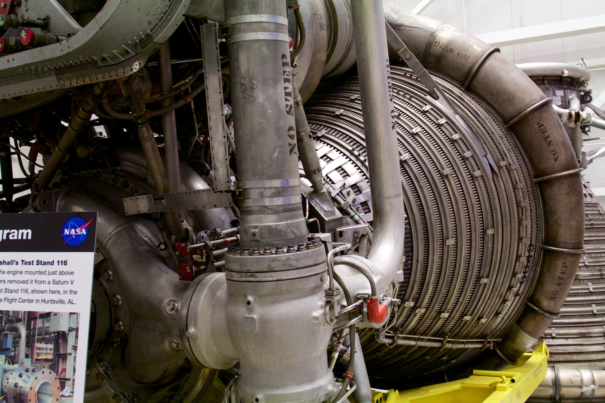
F-1 Rocket Engine – Developed by Rocketdyne in the 1950s. Five F-1. 16 Pics about F-1 Rocket Engine – Developed by Rocketdyne in the 1950s. Five F-1 : F1 Rocket Engine Diagram, F-1 Engine Thrust Chamber | Rocket engine, Apollo spacecraft, Apollo and also F1 Rocket Engine Diagram.
F-1 Rocket Engine – Developed By Rocketdyne In The 1950s. Five F-1
 www.pinterest.com
engine rocket rocketdyne engines f1 saturn space liquid power nasa developed five apollo stage were building 1950s medium center
New F-1B Rocket Engine Upgrades Apollo-era Design With 1.8M Lbs Of
 arstechnica.com
engine thrust rocket apollo f1 series 1b barrel tubes upgrades lbs 8m era chamber upper nozzle tightly hoops packed bound
Saturn Launch Vehicle Information
 www.alternatewars.com
saturn rocketdyne engines diagram space engine 1964 chamber lifters orbiters landers dev count solutions low thread ratio launch left right
Aerojet General Space Engines (1942-2013)
 alternatewars.com
engines cycle space engine rocket fuel dual aerojet liquid aj
F1 Rocket Engine Schematic - Wiring Diagram
 alohagrace.blogspot.com
engine rocket f1 manual schematic technical 1a supplement
F-1 Engine Thrust Chamber | Rocket Engine, Apollo Spacecraft, Apollo
 www.pinterest.com
engine thrust chamber rocket diagram manifold drawing space apollo spacex engines f1 blueprints pixel turbine bell cooling visit
F1 Rocket Engine Diagram
engine rocket injector diagram merlin f1 saturn fuel orifices
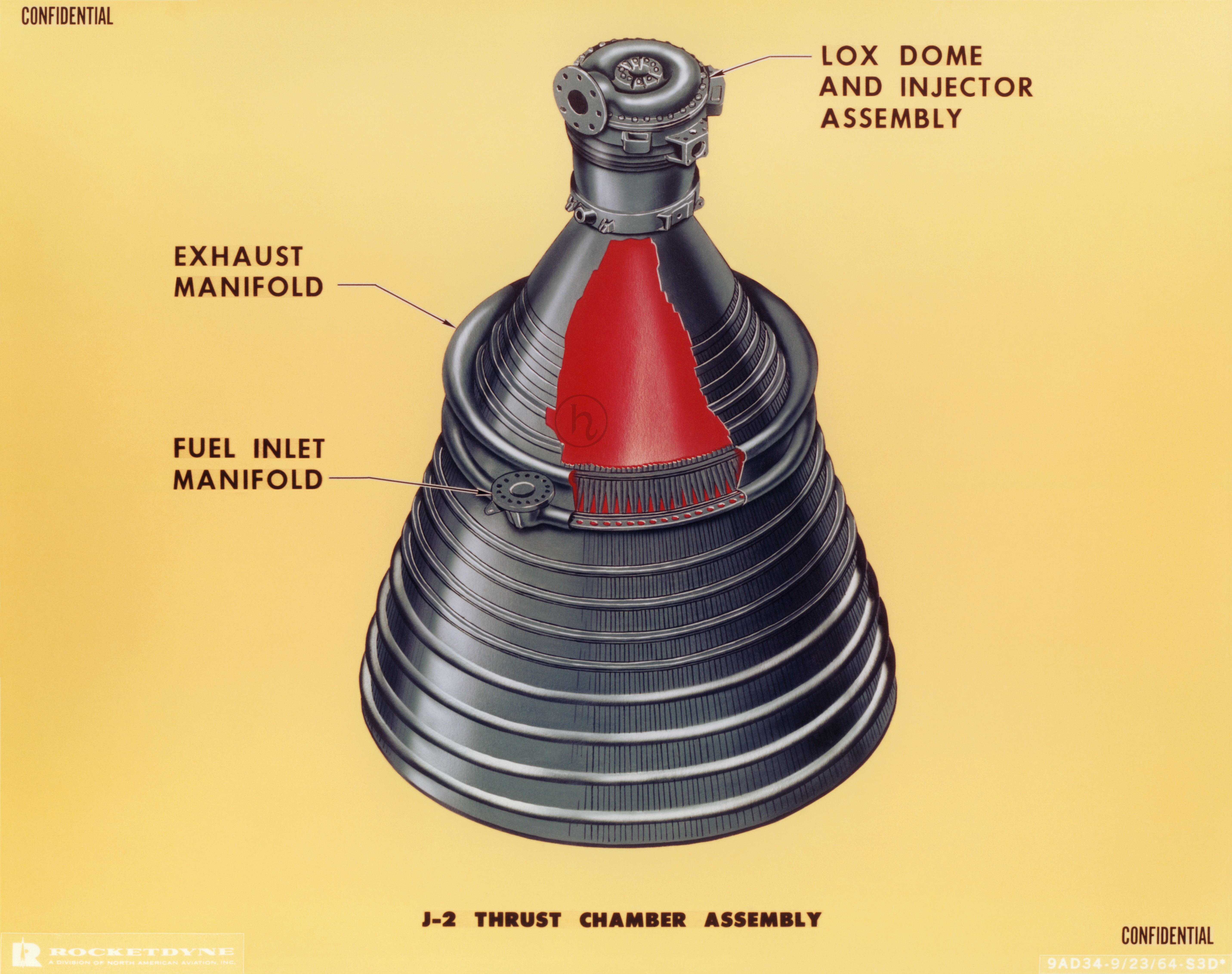
J-2 Rocket Engine Thrust Chamber
 heroicrelics.org
chamber thrust rocket engine ratio assembly expansion pixel version
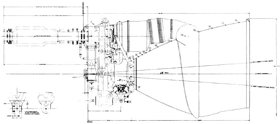
F-1 Rocket Engine General Configuration
 heroicrelics.org
rocket engine thrust chamber cfg gen
Category:F-1 (rocket Engine) - Wikimedia Commons
 commons.wikimedia.org
rocket 1606 1719
Rocketdyne F-1 - Wikipedia
 en.wikipedia.org
rocket engine rocketdyne apollo saturn engines engineering weight flight nasa space wikipedia pounds specifications recovery fuel diagram main recovered its
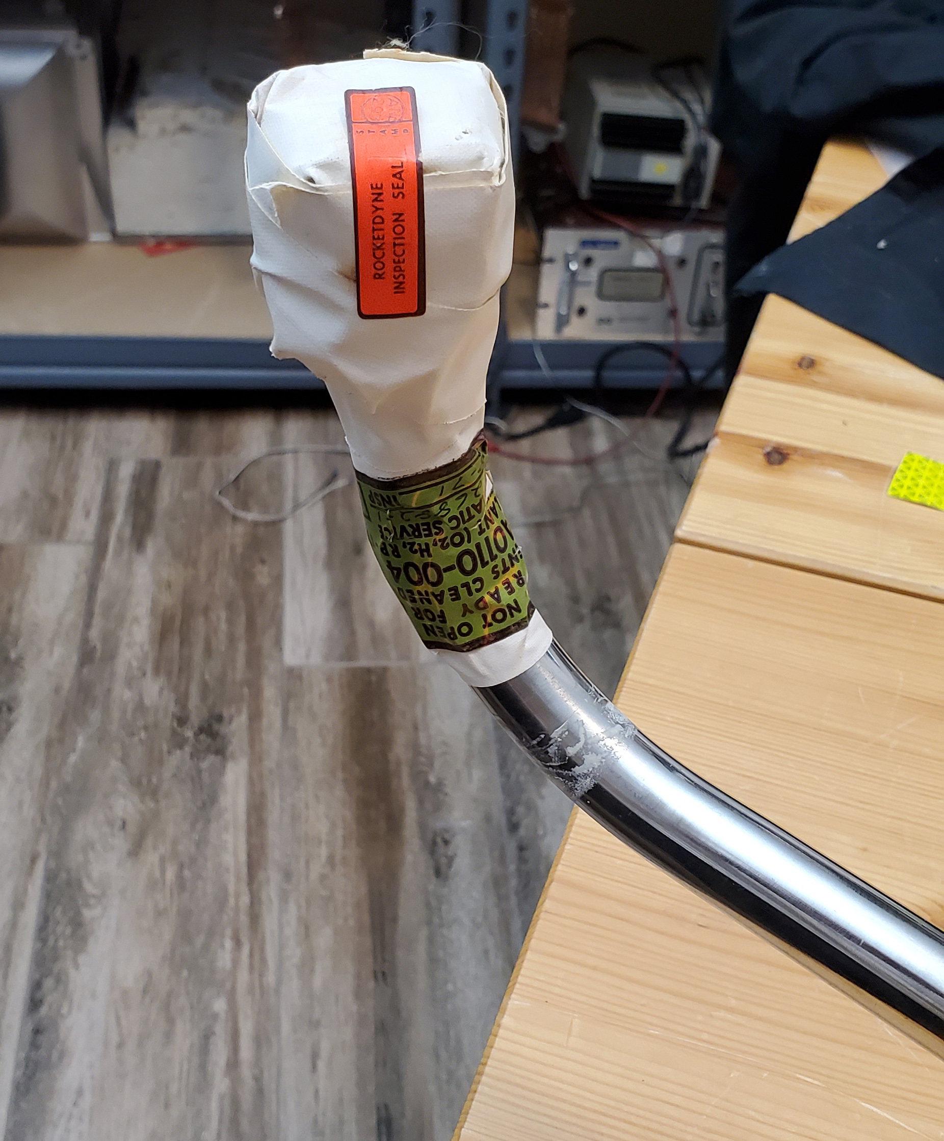
FS: F-1 Rocket Engine LOX Purge Hose - CollectSPACE: Messages
 www.collectspace.com
purge lox
Why Did The Saturn V Rocket Require So Many Parts (around 3,000,000
engine saturn rocket generator gas boeing flow does apollo parts fuel stage liquid engines second difference aircraft between ignition begin
F1 Rocket Engine Diagram
 formulaf1results.blogspot.com
engine chamber thrust rocket nozzle cut combustion saturn cutaway away f1 fuel joint schematic manifold engineering extension diagram turbine space
F1 Rocket Engine Diagram
 formulaf1results.blogspot.com
engine schematic f1 rocket diagram rockets simplified space
F-1 Rocket Engine G4049 Engine Vertical Installer Data Sheet
 heroicrelics.org
engine rocket vertical sheet installer data control pixel version vei
Engine rocket vertical sheet installer data control pixel version vei. Engine thrust chamber rocket diagram manifold drawing space apollo spacex engines f1 blueprints pixel turbine bell cooling visit. F1 rocket engine diagram